beam to beam moment connection design example
Design of Steel-to-Concrete Joints Design Manual II eg. If the frame is statically indeterminate the connections must have sufficient ductility to accommodate any inaccuracy in the design moment arising for example from frame imperfections or settlement of supports.
Moment Resisting Connections Steelconstruction Info
Moment Connections book provides guidance.
. This tutorial provides an AISC connection design example. Where y D2 5872 2935 mm. It has been said that since the other beam frames into the girder opposite the moment connection that beam will.
Bridge Construction Design Design and Construction Design Loads Design to BS 5950 Design to BS 8110 Design to EC2 Design to EC3 Foundation Design Geotechnical Design Materials Post Tension Retaining Structures Seismic Design Servisibility Design Special Designs Structural Detaling Structural Failures Testing. In statically determinate frames a partial strength connection adequate to resist the design moment is satisfactory. Local limit states for the column will be discussed and applied in a design example.
Design a bolted flange-plated FR moment connection between a W1850 beam and a W1499 column flange to transfer the following forces. Figure 9 Design Parameters. Show that the proposed welding scheme for this connection is adequate.
Common moment configurations either with the beam flange welded directly to the column or with flange plates connecting the beam to the column will be presented. It is important for the novice to become familiar with such connection types and their advantagesdisadvantages which are described in the subsequent sections of this chapter. This construction method reduces the demands on the connection by moving the hinge-point of the connection away from the column to the splice significantly reducing the stress concentrations at the beam flange weld.
Has been carried out as part of an investi gation sponsored jointly by the American Iron and Steel Institute and the Welding Research Council. A very easy to use spreadsheet for designing steel beam to beam endplate bolted splice connections subject to moment positive or negative axial load tension or compression and shear. In tests the first part of the moment rotational diagram representing the stiffness is usually linear.
1a is an example of a typical beam-to-column moment connection. Eurocodes - Design of steel buildings with worked examples Brussels 16 - 17 October 2014 Example Single sided beam-to-column joint configuration bolted end-plate connection M V 15 3 IPE220 HEB140 120 60 10 30 80 30 240 4 M16 88 140 p60 u10 5 w To be evaluated. Beam to column or to wall connections and The worked examples in Chapter 9.
The nuts should be placed on the inside of the column flange The beam web connection in both the beam and the column. Moment Connections Part 1. Moment connected beams Beam stubs can work well with this connection also.
Example 1 Design a bolted T-Stub moment connection for the beam shown on Figure 9 supporting both gravity and wind loads. However the linear elastic curve deviates from its straight line at low bending moments Wald Steenhuis 1993. Shear connections between I-shaped sections are some of the most common connections in steel design.
I have seen it designed both ways. The CivilWeb Moment Connection Design Spreadsheet suite is a powerful suite of steel design spreadsheets which can be used to design moment connections in steel frame structures. I attach an example not strictly to all your dims I use metric but shows the options needed to get the desired arrangement.
Therefore the web will carry 973761500 158 of the moment in the beam assuming an elastic stress distribution while the flange will carry the remaining 842. Beam Connection A stiffened seated Design Example A detailed example illustrating the de- W21x68 beam is connected to a W14x90 column for an R u equal to 125 kips 2 of 15 Composite Beam Shear Connection Design and Detailing Practices for Australian Steel Decks Executive Summary Efficient utilization of welded-stud shear. The two beams are in line.
I w 4765 3 10812 10 -4 9737 cm 4. There are resources available for the design of moment connections between wide-flange beams and HSS columns. The flange and web angle connection shown in Fig.
Figure 62 gives an example of a beam to column connection and its moment rotational diagram. Part 12 of the AISC Steel Construction Manual contains a discussion of moment connections to HSS columns and the AISC Design Guide 24 contains discussions of specific connections types the limit states to consider and include examples. One beam is a cantilever fastened with a moment connection to the girder.
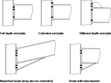
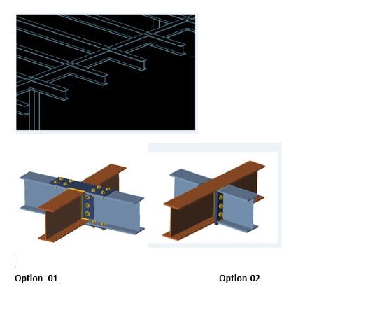
A w 4765 108 10. Joints in Steel Construction. 25 Design steps 8 3 WELDED BEAM TO COLUMN CONNECTIONS 42 31 Scope 42 32 Shop welded connections 42 33 Design method 44 34 Design steps 44 4 SPLICES 51 41 Scope 51 42 Bolted cover plate splices 51 43 Design steps 52 44 Bolted end plate splices 61 45 Beam-through-beam moment connections 62.
In moment-tree connections the stub is shop-welded to the column and spliced to accommodate the connecting beam. Allowable Vertical Reaction Ra 70 kips 21 kips 280 kipsAllowable Moment Ma 420 kip-ft 126 kip-ft 1680 kip-ft. Weld shear moment is.
The area of the web is. This session will address wind and low-seismic moment connection design. Can the other beam be a simple shear connection or does it have to be a moment connection.
Example IIB-1 Bolted Flange-Plate FR Moment Connection beam-to-column flange Given. Design moment resistance initial stiffness 0 1 10 10 M M J J. First use a Fin Plate joint on either beam maybe called Shear Plate outside the UK connecting the secondary beams to the main beam.
Weld second moment of area I xx is. It covers flush and extended endplates with two or four bolt lines and up to six bolt rows per endplate end. Then use the Moment Connection Beam to Beam on either side of the main beam.
Steel Specification ASTM A992 - Bolts ASTM A325 Loads. Example 2 Design a. The connection is to be designed to transmit a bending moment of 500 kN m and a shear force of 300 kN.
Effective length of weld is. 25 Cut-Out Plate Connection Example 26 Check 58 thick cut-out plates 50 ksi Find plate dimensions Controlling plate location is adjacent to column Find ws dimension based on tension in the plate Tu M u12d tp 183 k ws T uΦ2F ytp 325 inches. Beam-to-ColumnConnections BEHAVIOR AND DESIGN OF STEELBEAM-TO-COLlillNMOMENT CONNECTIONS by Joseph S.
Leg length of weld s 10 mm. The flange plate width in this example was 70 in but the width used in the calculations is 750 in hence the difference in values. The suite includes 12 separate design sheets for the design of all commonly used moment resisting connections including end plate connections beam to beam spliced.
Dead Moment MD 20 ft-kips Live Moment ML 38 ft-kips Wind Moment Mw 82 ft-kips.